Your question should read:
How do I scale a 0 to 5 V signal to -10 V to +10 V?
First write the conversion formula:
Vout = 4 * Vin - 10
Testing the formula gives the following:
- Vin = 0.0 V ==> Vout = -10 V
- Vin = 2.5 V ==> Vout = 0 V
- Vin = 5.0 V ==> Vout = +10 V
You will need an op-amp circuit to create this function. In addition you will need a +12 and -12 V supply.
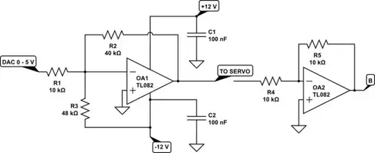
simulate this circuit – Schematic created using CircuitLab
How it works:
- OA1 is an op-amp wired in an inverting summing amplifier configuration. We'll address the inversion later but for now all the answers will be "upside-down". The gain is set by -R2/R1 = -40k/10k = -4. If we feed 1 V in from the ADC we will get -4 V out.
- R3 provides a negative input. The gain will be set by -R2/R3 = -40k/48k = -5/6. Since it's connected to -12 it will contribute +10 V to the output.
- The actual output will be the sum of the two: in our example, +10 - 4 = 6 V.
- C1 and C2 provide noise filtering for the op-amp. Place them close to the chip.
Now, what to do about the inversion? We have three choices:
- Fix it in the micro controller code. Set +5 V as maximum reverse speed / torque. Set 0 V as maximum forward speed / torque.
- Fix it in the servo amplifier and tell it to reverse its command signal.
- Fix it in the electronics. By adding another inverting op-amp we can turn the signal the right way up.
The TL082 opamp suggested has two op-amps in the one 8-pin package.
Ref: Inverting Summing Amplifier.
Servo Enable
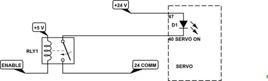
simulate this circuit
Delay the servo enable until the micro controller has initialised and all other functions are ready. See manual Section 3.2.3, page 73.
Note that this is a simplified relay drive schematic. You need a transistor drive and a snubbing / flyback diode around the relay so one of the small 5V relay boards would be a good solution as they are already built in. An opto-isolator would be simpler.
Ensure that safety circuits (guarding and e-stops) are correctly wired using safety-rated components (and not only, for example, the micro).