Alright, you say "I am new to analog design" so I'll try to be thorough, following signal flow...
On the input I see 3x 330k resistors in series, so at first i thought this must be a high voltage input, but the division ratio with R36 is too low for that. AMC1301 datasheet says "±250-mV input voltage range" so with a 1:4 divider this gives a ±1V input voltage range. Also that chip has a fixed gain of 8.2 and a max output voltage of 5V, so AMC1301 input voltage range should only be ±0.6v, give or take depending on what the AD711 does and if the ADC goes all the way to 5V input.
There is a 1µF cap "C29" on the input, with the 330k resistors this forms a lowpass filter at a pretty low frequency, below 1Hz. So this is intended to measure DC.
Make sure this cap is not piezoelectric, which means no Class-2 ceramics (X7R and the like), so a film cap. Otherwise you are building a microphone. This applies to every cap in the signal path. C0G is best if available, next best is film caps.
It is not clear what L1/L2 do, if you want a common mode filter it should be at the input, not in the middle of the circuit.
Now there are a few contradictions:
If you want to measure DC, then why select an expensive highspeed ADC? A sigma-delta ADC could be a better choice, cheaper, plus the integrated digital filter will get rid of 50-60 Hz hum for free.
That AMC1301 isolated amplifier looks like a nice part, but it has quite substantial offset and gain error:
offset error and drift: ±200 µV at 25°C, ± 3 µV/°C
gain error and drift: ±0.3% at 25°C, ± 50 ppm/°C
If fullscale input is ±0.6v then the offset represents 87 ADC LSBs and the gain error represents a few hundreds LSB. Why a 18 bit ADC then, unless maybe you zero out the offset at the beginning of the measurement via some other means? There's something weird going on.
OK, next is the AD711, I guess it takes the output of AMC1301 and recenters it on the ADC reference voltage. The ADC already includes a programmable gain amplifier that will do this job, so I'm not sure why the AD711 is there.
The AD711 is powered from ±12V but the ADC's input range is actually +/-20V so that's okay.
The split between AGND and DGND at the ADC is an excellent way to add noise into the signal. If the only digital component on the board is the ADC, then the whole ground plane should be solid, uncut, and it is all "analog ground".
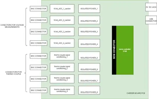
The two digital isolators cause some head scratching, because the REFIO line from the ADC is connected directly to the digital connector, bypassing the digital isolators, which means the ADC isn't actually isolated from the connector. What are those digital isolators doing? If the goal is to prevent noise on the digital lines from getting into the ADC, then don't use isolators, an old 74HC buffer will do the job just fine for a much lower cost, and is most likely not required anyway.
The same applies to the two isolated power supplies on top of the schematic.
First, why put two isolated supplies in series?
Second, the ADC is connected to the IO connector via REFIO/REF_1 pin, making the isolation useless. Also if ADC ground is not connected to the IO connector ground, the voltage on REF_1 will be referenced to nothing.
Then, AD711 is powered by +/-12V from the connector on the bottom left, so AD711 is not isolated from this connector... then why use isolation amplifier AMC1301 if the isolation is bypassed via the power supplies?
Also, +/-12V from the connector on the bottom left are referenced to AGND1 but on the AD711 side they are referenced to AGND3 which is apparently not connected to AGND1. This won't work, and if there is enough common mode voltage between AGND1 and AGND3 this will also appear on the +/-12V relative to AGND3 and fry both the opamp and the ADC, and potentially whatever is connected to REF_1 signal on the other side of the IO connector.
Speaking of REF_1, I also see it lurking in the connector on the bottom left, which again defeats isolation. Also it is not referenced to any ground.
So, as you see, there are a few... problems... here.
First you need to clearly specify what should be isolated from what. If the pin "REF_1" on the bottom left input connector absolutely must be connected to the pin "REF_1" on the middle right IO connector and also to the ADC reference voltage, because these systems all need this reference voltage, then... every ground will have to be connected together so REF_1 is referenced to the same GND everywhere, and then no isolation is possible and you have to find another way to get rid of the common mode.
--
From your edit:
BNC connectors aren't ideal for isolation, they are meant for shielding and they're pretty good at it. The cable shield, the shell of the coaxial connectors, and the metal enclosure make a continuous shield over the central conductor so the signal is protected from noise. But, of course, that only works if the shield is grounded to the enclosure or the ground plane, which means the connector shields usually are not isolated from each other. In the usual lab instrument, all the BNC shells are screwed into the chassis, or go directly to the ground plane.
If the goal of isolation is to deal with high voltages, then the coax shield and connector shells shouldn't connect to this high voltage, because it is exposed to fingers and handled frequently. So if you're going to handle high voltage you really need something safer.
I guess you should explain what kind of voltages or signals you want to measure (voltage range, frequency, etc) and why you need isolation. If all the signals have a common ground reference, but sit on different common mode potentials, then maybe what you're looking for is not isolation, but differential inputs.
For example if you want to measure the current in the positive output of a low voltage power supply, by measuring the voltage across a shunt resistor, this signal has a common mode equal to the voltage at the output of the power supply, so a differential input would be adequate. But there is no requirement to isolate the grounds, the ground of the power supply under test can be connected to the instrument ground.
Isolation can be a way to get differential inputs too, but... another reason why I don't like the idea of isolating BNCs is that, in the example above, suppose you wire a coax on the shunt resistor you want to measure voltage on. So, the center conductor of the coax is on one end of the shunt resistor, and the shield on the other end. Now, the shield and the shell of the connector are at the power supply voltage. If it's 12V then it is safe, but if the BNC shell touches another BNC shell that is at another voltage, then it makes a short circuit. I mean, BNC cables usually look like this:
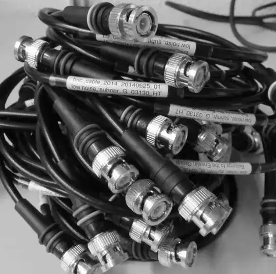
This is going to end with insulating tape wrapped over the connectors...
So, what do you want to do exactly?
WARNING: I see you use thermocouples. To read a thermocouple you have to do cold junction compensation, that is to compensate for the temperature of the junction where the thermocouple wires connect to the instrument. You can't do that with BNCs because there is no temperature sensor inside the connector. Also in the BNC connector's the part that contacts to the shield is a different metal than the center pin, so you'll get thermocouple offset voltage and measurement errors...


