0

I was wondering if there was a component that would only let current flow if it was above a predetermined voltage.

I am building a subsystem for my project, which is an open door sensor that uses a microcontroller. I am running the circuit at 5 V, and I want an LCD display to display when it is time to change the batteries. The circuit will not have an external power supply to reference the voltage to when testing the batteries. Circuit diagram 
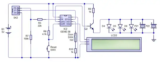
This is my circuit so far and it only needs this last bit. Whilst the microcontroller can run at as low as 3 V, the LCD needs 4.5 V - 5.5 V to work, so 4.5 V will be my minimum voltage, but I would like to know in advance, so maybe a bit higher.

Any help in understanding this would be greatly appreciated.

Alex Hajnal
  • 1,334
  • 9
  • 19
  • 2
    Anyway, you're probably still barking up the wrong tree – describe exactly what problem your "battery tester subsystem" is supposed to solve – arbitrary bets this is not the solution. – Marcus Müller Apr 21 '20 at 21:40
  • It would help if you could give a little more detail on what you are trying to do (battery voltages, required comparison voltage, required current). You might also like to read about precision voltage references, which are designed to work with a variety of input voltages. – David Apr 21 '20 at 21:40
  • Malted Wheaties - As Marcus just commented, don't start guessing about components. Also, this is a partial duplicate of the question you just asked. If you have more details, you should edit that earlier question, add those details there and delete this one, instead of asking more and more new overlapping questions. Thanks. – SamGibson Apr 21 '20 at 21:42
  • A Zener diode starts to conduct fairly abruptly, but has a finite "knee". How sharp a cuttof do you need? – DrMoishe Pippik Apr 21 '20 at 22:27
  • 1
    Anything from a zener diode to a comparator could answer your question. We need more details about your circuit and exactly what you are trying to do to give a helpful answer. – evildemonic Apr 21 '20 at 22:36
  • If you've got a microcontroller in the system, use its analog input. – pjc50 Apr 21 '20 at 23:06
  • 1
    There are a number of existing questions here which deal with this topic. 1, 2, 3, etc. The basic idea typically is to divide your battery voltage down so that it's in the range of your microcontroller's ADC input. – brhans Apr 21 '20 at 23:40
  • 1
    @MaltedWheaties Please add the additional information to the question's body. Don't post lengthy comments with information vital for understanding your question. – Ariser Apr 22 '20 at 15:33
  • A low voltage comparator with set reference can be used to indicate low voltage battery indication – Leoman12 Apr 22 '20 at 17:08
  • @Leoman12 I do not have a reference voltage, as the tester is being powered off the same source as the battery to be tested. As the battery voltage decreases over time so too will the 'reference voltage' – Malted Wheaties Apr 22 '20 at 17:23
  • @Malted Wheaties True but you can use a circuit that would indicate low voltage prior to a point when battery is unable to provide sufficient power to indicator circuit. Also you can use a low voltage reference ic or low voltage Zener that can be generated which can still work when voltage is low. For example if worse case is 3V to be indicated then 3V would still be fine for some low voltage reference voltage ICs – Leoman12 Apr 22 '20 at 23:32
  • What power source are you using? If you're running off of batteries you'll want some kind of regulator (either a boost, boost/buck or LDO as appropriate) to get a stable 5 V. – Alex Hajnal Apr 23 '20 at 00:05
  • 1
    @MaltedWheaties most microcontrollers with an ADC will also have an internal voltage reference to solve this problem. – pjc50 Apr 23 '20 at 07:51

2 Answers2

2

You'll want to use a voltage reference along with an ADC or analog comparator. Voltage references work kind of like an LDO voltage regulator; the difference is that they put out a very stable and accurate voltage (but very little current). The following circuit will do the job:

Circuit using comparator

The two resistors will supply half the battery voltage to the comparator. The chosen voltage reference is 1.6 V (half of a LiPo's very low battery level of 3.2 V ). The comparator will output true if Vbat1 drops below 3.2 V. Alternatively, one could use an ADC that allows a reference voltage as an input:

Circuit using ADC

In this case the voltage reference is chosen to be over half the maximum battery voltage (2.5 V × 2 = 5.0 V). The output of the voltage divider is measured by the ADC using 2.5 V as the top of the measurement range. To get the actual voltage plug the ADC output value \$N\$ into the following: $$ V_{bat} = { { 2 \times N \times V_{ref} } \over { 2^{resolution} - 1 } } $$ The result is the measured battery voltage \$V_{bat}\$ in volts. \$V_{ref}\$ is the value of the voltage reference (in volts) and \$resolution\$ is the resolution of your ADC (in bits). Many popular microcontrollers and development boards have built-in ADCs with support for external voltage references (the Teensy 3.x and Feather M0 boards come to mind).

For either of the above you should choose a voltage reference that's appropriate for your power source. LiPo batteries, for example, typically max out at 4.2 V, spend most of their useful life at 3.7 V, and cut out completely at 3.0 V. Alkaline batteries, on the other hand, start out at 1.5 V then end their useful life around 1.15 V (IIRC). Your typical NiMH will start out at 1.3 V and dip to a tad under 1 V before they're unusable (again, IIRC).

I used LiPo batteries for the examples above; regardless of the battery technology you use you'll want to feed it to a 5 V regulator2 that can then power the rest of your circuit.

1 \$V_{bat}\$ is the raw battery voltage, not the output of your voltage regulator.

2 For LiPo batteries you'd use a boost regulator.

Alex Hajnal
  • 1,334
  • 9
  • 19
0

4.5V will be my minimum voltage, but I would like to know in advance, so maybe a bit higher.

You could use a Zener diode and resistor. The Zener diode drops a relatively fixed voltage, so as the power supply voltage drops the zener output voltage drops proportionally faster. The MCU has an ADC which measures the ratio between its input and the power supply voltage, so the ADC count reduces as the battery voltage drops.

schematic

simulate this circuit – Schematic created using CircuitLab

I simulated this circuit in LTspice with battery voltage dropping from 6 V to 4 V, and got the following results (blue = battery volts, green = ADC input, red = ADC count):-

enter image description here

8 bit ADC count varied from 71 at 6V to 20 at 4 V, an average of ~1 count per 40 mV. At 4.8 V it was 41. This should be accurate enough to show battery voltage with a resolution of 0.1 V, or as a bar display with 10 or more segments.

Only one problem - you appear to be already using all the pins on your MCU! You may be able to reconfigure the PR pin for ADC input. If so then you will need a jumper or switch to select between programming the MCU and reading the battery voltage.

Bruce Abbott
  • 56,322
  • 1
  • 48
  • 93