0

I'm currently assessing sub sea pumped hydro capabilities, and need to use the flow rate in order to calculate power output. I can calculate the energy storage capacity using E = mgh:

$E=mgh = 25675000 \times 9.81 \times 200 = 50374 \ \mathrm{MJ} = \frac {50374\text{MJ}}{3600} = 13992 \ \mathrm {kWh}$

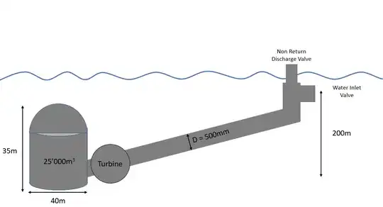
However, I don't know what the flow rate from open sea into the pipe would be. In the model below, the top of the pipe has a valve that will open to let seawater in during the power generation stage, down through a 90/10 Cu/Ni pipe, through a turbine and subsequently fill up the vessel, which is located 200 m below the inlet (Head = 200 m). Vessel design doesn't take into account the pressure at this depth through use of a bag seen here.

What would the best way to calculate the flow rate to use in theoretical power calculations, since the sea is an open reservoir?

  • Head = 200 m
  • Pipe Length = 1594m (assuming a straight path between elevations)
  • Vessel Volume = 25,000 m3
  • Seawater Density = 1027 kg/m3

These variables can all be changed this is just preliminary/theoretical.


enter image description here

Kuriosity
  • 11
  • 4
  • What exactly does the sentence pressure is negated through a bag mean? Water flows when there's a pressure difference. with the bag system in place as on pg 8 of the presentation there will be no flow. It appears you idea won't work. – mart May 03 '21 at 07:41
  • @mart Sorry I just meant that the storage design doesn't need to consider the pressure at the seabed – Kuriosity May 03 '21 at 07:51
  • i started typing an answer but the fact that you include a pipe in your scheme and that you didn't say *anything* about what's in the tank before water flows in tells me that youlack basic understanding of the issue. Maybe someone else is more willing to do basic schooling. look at head loss equations on wikipedia but mostly understand what defines the pressure at both ends of your pipe. – mart May 03 '21 at 08:24
  • 3
    Does this answer your question? [I want to determine the flow rate and required turbine size for an offshore hydroelectric scheme and need help](https://engineering.stackexchange.com/questions/42906/i-want-to-determine-the-flow-rate-and-required-turbine-size-for-an-offshore-hydr) – Solar Mike May 03 '21 at 08:26
  • @mart Sorry I should have said that the tank is filled with seawater to begin with in it's initial state, when demand for energy is low the turbine ideally would pump the water up and out through the discharge valve creating potential energy. When energy demand is high water would flow back through the turbine and fill the tank, in the similar way that pump storage hydro works. I'm aware of Darcy-Weisbach etc, but it's the actual initial velocity and flow rate that I'm having a problem with due to it being in the ocean – Kuriosity May 03 '21 at 08:32
  • You need to add an air inlet to the top of the undersea tank as in Riser A of your previous question. It only has to be big enough that it doesn't restrict the water flow any more than you want it too. (Now I've doubled your problem into a water flow and and air-flow problem.) You can reduce friction losses by making the pipe vertical as that's the shortest route from inlet to tank. The turbine should go below the tank if you want to use it to pump the water out again. – Transistor May 03 '21 at 11:15
  • cool concept!! seems like ordinary pipe flow would be good enough to estimate pressure drop. An air flow path of negligible P drop won't add nearly as much to material mass compared to the water flow path and can probably be left out of 1st-order estimates. Even the water pipe might be tiny mass compared to the construction of the tank/dome ... depends on use cycle parameters – Pete W May 03 '21 at 13:28
  • Why the two valves at the end instead of just an open end with a trash rack? – TooTea May 03 '21 at 14:49
  • 2
    Also, what is the point of the long pipe in the first place? Why not just have the turbine inlet/discharge right at the bottom, making the whole system much more compact and eliminating pressure losses? The water down there is going to be very similar to the water near the surface. – TooTea May 03 '21 at 14:55
  • Also want to say this is all purely theoretical, because it's not based off of actual bathymetry, just an ideal scenario. Was just looking for a base of what kind of flow rate to expect, but I'll probably just generate predicted power output at different flow rates because the head loss could always be different depending on the pipe dimensions – Kuriosity May 04 '21 at 02:46
  • The scheme in the link above does nothing as far as I can see. You've got water at sea level supposed to run down a pipe and discharge into the sea at depth. How's that supposed to happen? – Transistor May 04 '21 at 11:48
  • @Transistor I was just about to try and justify it but I've realised my glaringly obvious mistake, well that's that scrapped, deleting it to save further embarrassment – Kuriosity May 04 '21 at 11:58
  • @mart Could you verify if the answer I submitted is correct? – Kuriosity May 10 '21 at 15:34
  • Update: welp, whole idea is invalidated due to Torricelli's Law – Kuriosity May 15 '21 at 19:18

2 Answers2

0

You can't pump water into the ocean and gain the potential energy of it again like this. In this example, if you pump water out, the tank fills with water anyway because it's really just a balloon. If you somehow had a cave you could pump out then it's a simple head calc, using the total pipe equivalent length.

Basically, putting this in the ocean instead of below a lake (like this is normally done) just makes all the materials more expensive and difficult to maintain.

Tiger Guy
  • 5,369
  • 6
  • 17
  • I think OP has in mind a giant tank ("cave")? it would have to be comparable in size to a resirvoir used with a hydroelectric dam. However, roof of dome would be bigger than wall of conventional dam?! So can't scale big, but maybe could have niche applications... I'm keeping open mind, considering that crazy Swiss concrete block + crane energy storage scheme someone posted a month or two ago seems to've got funded – Pete W May 05 '21 at 22:39
  • @PeteW you're correct! The tank would act as the lower reservoir, with the pipe running the natural shelf to the wind turbine. It'll have to be a large drop in order to justify the length of pipeline that would be needed, so currently looking at coastal Spain in order to try and keep within the 1:12 L/H ratio that's recommended for hydro storage schemes to be viable, like the Avile's Canyon or something. There's only one or two spots in Scotland that could possibly work. It's only a working theory anyway, it's more to balance out wind farm inconsistencies than be it's own standalone system – Kuriosity May 05 '21 at 23:43
0

I've had a go at calculated the pressure loss along the pipe, can someone verify this?

A 5MW Francis turbine has been chosen using this;

So in generator mode, the rated discharge will be:

$$P_g=\rho \times g \times h \times \eta_g \times Q_g$$

Rearranging for Q while assuming generator efficiency is 0.9 gives:

$$Q_g = \frac{P_g}{\rho \times g \times h \times \eta_g} = 2.7599m^3/s$$ (Can generate rated capacity for 5.03 hours)

Rearranging the formula for pump mode to find Qp;

$$Q_p = \frac{P_g \times \eta_p}{\rho \times g \times h \times} = 2.2355m^3/s$$ (Can be operated for 6 hours)

Assuming pump velocity (vp) to be 5m/s, required diameter (d) is found using:

$$A=\frac{Q}{v}$$ then $$ A=\pi \times \frac{d^2}{4}$$ therefore d = 0.754m.

Reynolds Number:

$$Re = \frac{u \times d_h}{v} = 362500$$

So flow is turbulent.

Reading from Moody chart and using Colebrook equation to check, friction coefficient (f) = 0.0147.

Therefore via Darcy Weisbach, Pressure Loss = 399 kPa and Head Loss = 39m.

Have I done this correctly or is there something glaringly obvious that I've missed again?

Kuriosity
  • 11
  • 4