I have a software sending bitmap data to an Arduino Pro 5V 16MHz 328P that drives an LED display (sketch). This works using the USB-Serial adapter for the Arduino Pro with baud rates up to 500000 Baud. Now I wanted to switch to Bluetooth...
I tried connecting a 5V HC-05 module (set to 230400 Baud 8N1) to the hardware RX/TX pins on the Arduino Pro (Pins 0/1) and connect the PC to the Bluetooth serial port wirelessly (e.g. /dev/rfcomm0 on Linux). My problem is that I can receive data on the PC side using a terminal (the 'Ada' string is received), but nothing is displayed on the LED display. I have tried connecting an oscilloscope to the RX/TX pins on the Arduino and Data is arriving from the HC-05 module TX pin to the Arduino RX pin.
When the USB-Serial adapter is connected to the same pins (0/1 instead of the regular pin header) it still works as before, so there should be no connection issues.
What I tried was adding a 5kOhm resistor from the Arduino RX line to ground. (I found this hint somewhere here), but no dice...
I'm not sure what's wrong, because communication IS working over the USB-Serial adapter. Any ideas on what to try?!
-
1Start by using reasonable baud rates! Whatever you think you are accomplishing by trying to make one piece of the system so fast, is almost certainly not going to result in meaningful improvement overall, yet vastly increases the change that the system won't work at all. – Chris Stratton Jun 01 '15 at 00:44
-
There's a few things I can think of that may be causing your issue. First, though, a few questions: (1) Which version of the Arduino Pro are you using (168, 328P, voltage, frequency, etc)? (2) Are you saying that you can connect the PC to the Bluetooth serial port via a USB cable or via a wireless Bluetooth link (a little confused by the wording)? (3) What model of the HC-05 are you using (I know you said 5V, but I've come across many variations of this device - a link of where you bought it would be great). Hope I can help once you have a chance to answer these questions! – Mlagma Jun 01 '15 at 03:07
-
@ChrisStratton: The HC-05 advertises Baud rate up to ~1MBaud, so imo 230400 is reasonable. Also it works with the USB-Serial adapter connected to the same pins. – Bim Jun 01 '15 at 08:45
-
@Mlagma: The model is an Arduino Pro 5V 328P 16MHz. I "connect"/pair the PC to the HC-05 wirelessly and then plug the module into the RX/TX pins (Pins 0/1) on the Arduino. The HC-05 Module is a regular board with a 5V level-shifter-breakout (very common). Sorry, but I don't have a link anymore. What I tried was adding a 5kOhm resistor from the Arduino RX line to ground. (I found this hint somewhere [here](http://arduino.stackexchange.com/questions/790/corrupted-output-from-hc-05-bluetooth-module)), but no dice... – Bim Jun 01 '15 at 08:55
-
I have in fact used another HC-05 (no level shifters, 3.3V) sucessfully with an Arduino Due, plugging it into hardware Serial1 (Pins 18/19) and using the Dues' native USB port as a serial port to transfer text PC->HC-05->Arduino->PC back and forth. Even at 230400 Baud. – Bim Jun 01 '15 at 08:57
-
I have now tried connecting an oscilloscope to the RX/TX pins on the Arduino and Data is arriving from the HC-05 module TX pin to the Arduino RX pin. I guess the sketch is not working properly with the HC-05 connected, but I'm not sure why... What could I be missing? – Bim Jun 01 '15 at 12:32
-
1No, 230400 is **not reasonable** unless you have verified for a fact that both your devices can generate the necessary timings signals **accurately**, which a little math would suggest an Arduino cannot. – Chris Stratton Jun 01 '15 at 20:51
-
@Chris: I did not say you don't have a point. I know you're referring to [this problem](http://arduino.stackexchange.com/questions/296/how-high-of-a-baud-rate-can-i-go-without-errors). The error at 230400 should be ~8%, which is way off. I'll try with a lower bit rate. – Bim Jun 02 '15 at 10:58
-
115200 should be more than enough. – Avamander Jan 28 '16 at 23:20
-
For everyone? You are probably joking and mean "640k". And no, it is not. I have too many LEDs for the Baud rate... – Bim Jan 29 '16 at 11:25
-
Have you actually calculated how many bits you actually need? – Avamander Jan 29 '16 at 17:16
-
I have ~600 LEDs * 3 color * 8 bit resolution = ~14400 Bit / frame. This amounts to max. 8 frames/s for 115200 Baud, which is not enough. With 230400 It'd be ~16 frames/s, which is usable for me. I am testing simple compression algorithms too, so I can reduce the amount of data a bit, but ~10-20% size reduction will be the maximum. – Bim Feb 01 '16 at 09:20
4 Answers
A simple 10k/20k voltage divider is enough to bring the 5V arduino logic-level voltage down to ~3.3 for the HC-05. It worked for me anyway.
The default baud rate for HC-05 is 9600 baud. So unless you've changed this with AT- commands you will run into issues. Although I read that some boards default to 38400 - best check your documentation. All the cheap HC-05 boards I've tested default to 9600.
- 773
- 5
- 12
-
Communication works up to 115200 Baud, but not more. The goal was to get higher Baud rates... – Bim Jan 28 '16 at 15:19
-
@Bim - My HC-05 doco says *my* HC-05 hardware is only good for up to 115200. Hopefully yours is a better brand. – Kingsley Jan 28 '16 at 23:18
-
Can you provide a link? A quick look in [http://www.instructables.com/files/orig/FOR/4FP2/HKZAVRT6/FOR4FP2HKZAVRT6.pdf](here, page 8) says it should allow up to ~1.5MBit, which makes sense, because Bluetooth 2.0 does. I also tried with two different modules. – Bim Jan 29 '16 at 11:24
The HC-05 requires a 5V power supply and 3.3V logic. Using SoftwareSerial might be easier for you as you can use pins 8 and 9 rather than 0 and 1, because there can be issues with the USB. Are you transmitting the data you think you are, might Big/Little Endian be an issue? I can get two HC-05 devices to communicate when they are connected to the PC via serial port adapters. However when I replace the receiver with a HC-05 connected to an UNO I get intermittent garbage received. So I suspect there may be some sort of problem with PC->Arduino.
- 5,617
- 1
- 14
- 31
-
My HC-05 has level shifters, so it it suitable for 5V. Software serial is no option, because it is just too slow and blocks the Arduino. There should no issue with USB, because the Arduino Pro does not have USB. I don't think the Bluetotth module can change the endianess of the data. I'm interested what that "some sort of problem" is... – Bim Jun 01 '15 at 14:59
I've run into similar issues with the Arduino and serial communications - it's quite a pain.
There really shouldn't be an issue with your sketch if PC->USB->FTDI->Arduino is working since the same protocols are used (UART is UART, after all).
In regard to the BAUD rate, sure, 230400 should work just fine. For purpose of testing, though, I would slow it down to a measly 9600 or something like that just to rule out any possible issues. (Plus, if I remember right, 9600 or ~11000 is the rate at which it operates when being programmed via AT commands).
Now these are my thoughts on what the problem may be:
You said several times that you have a 5V HC-05 with level shifters. The HC-05 chip itself operates on 3.3V, so typically there is a voltage regulator on the breakout board dropping the voltage down to 3.3V for the Vcc pins and whatever else is pulled high on the chip.
However, I have never seen an HC-05 on Amazon, Sparkfun, or Ebay that actually has a true logic-level shifter on the board itself. Instead (and this is true from my experience with Ebay sellers who claim logic-level shifting built in), there is a voltage divider on the HC-05 RX pin that allows you to send a 5V signal without external resistors. But this isn't bidirectional, so your TX pin still has a logic high level of 3.3V. In short, I think your HC-05 chip really doesn’t have a logic-level shifter.
You may be thinking I’m totally wrong about this, and I very well could be since I don’t have your module in front of me, but just hear me out by reading my reasoning below.
(1) You said you can receive data on your PC. This means the HC-05 is receiving data from a 5V signal and successfully converting it to 3.3V. Great. That works!
(2) You said you were able to get an HC-05 (presumably the same model) to work with an Arduino Due in both directions. The Arduino Due operates on 3.3V, so its logic high threshold is around 2.1v.
(3) On the 5V Arduino Pro, the minimum logic high threshold is (0.6)*Vcc -> 3V. So if the HC-05 is transmitting a signal with a logic high of 3.3V, the Arduino is barely registering it. Factoring in resistance and noise, your signal is probably less than 3.3V. (In fact, my HC-05’s usually push out a signal of ~3V).
Reading that you can see a signal on the HC-05 TX line, but the Arduino is not registering it, I’d bet your signal is below the threshold.
So, I’d fire up your oscilloscope again and check the peak voltage to see what it is.
Additional (Response to "what can I do?)"
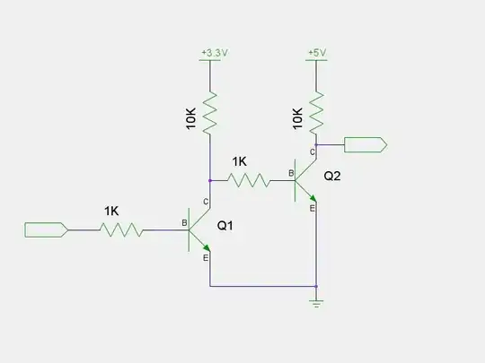
You have a few options. The best option would be to use a bidirectional 3.3V-5V level shifter, but not many people have those laying around. If you happen to have some common components, you could try building a makeshift level shifter like in the images below:
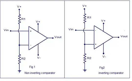
The first "level-shifter" is a a voltage comparator using an opamp. If you go this route, ground V-, tie V+ to 5V, and calculate a voltage divider for around 1.5V. (Note: use the non-inverting setup). A cheap TL272 from Radioshack should work.
The second level shifter uses two NPNs and is self-explanatory.
Note, though, that I haven't tried any of these setups nor know their frequency responses. However, the TL272 should handle signals into the MHzs, and BJTs handle high frequencies rather well. My gut tells me it should work, but just in case, I would use a low BAUD rate.
- 174
- 4
-
DAMN! You seem to be right! The HC-05 puts out ~3V on its TX line. The RX line shows a maximum of 3.8V. What can I do? – Bim Jun 01 '15 at 20:23
-
-
Thanks a lot! I don't have a TL272 (or other OpAmps) at hand and don't really want to build a level shifter for 3 channels (RX/TX/EN) right now, so I ordered a [bi-directional 4-Channel level shifter board](https://www.adafruit.com/products/757). I still have a 3.3V linear regulator lying around. I seem to have broken the EN/KEY pin of the HC-05, but have a working one for 3.3V. It should take a couple of days for the stuff to arrive and for me to try things out, but then I'll get back with the results... – Bim Jun 02 '15 at 11:08
-
The parts have arrived and I tried connecting the HC-05 to the Arduino Pro through the level-converter. The voltage levels are now around 4.5V. It all works well through bluetooth at 115200 Baud, but not at 230400 Baud.I also tried using a Arduino Due instead and connecting the HC-05 directly (TX0/RX0). As before, I can receive data on the PC side (The "Ada" status message), but no data arrives on the Arduino side... I'm at loss what to try to get higher throughput through the HC-05... – Bim Jun 10 '15 at 13:34
-
@Bim Just to be sure, it is working now in both directions at 115200 Baud? The problem is that 230400 isn't working? – Mlagma Jun 10 '15 at 22:27
-
Yes.It is working at 115200 Baud in both directions. I captured the waveforms of a bit for 115200 and 230400. The signal generated by the Arduino looks good, but that of the HC-05 is pretty crappy: [115200](http://s29.postimg.org/txnjokq6f/waveform_hc05_115200.jpg) [230400](http://s29.postimg.org/4qcnobn2f/waveform_hc05_230400.jpg) – Bim Jun 11 '15 at 07:12
-
A problem in the code could be that FastLED takes a lot of time in "show()" and due to that the serial port is overrun and data dropped... But at some point the code should recover. I uncommented the "while (Serial.available() > 0) { Serial.read(); }" loop (Line #83 in the sketch) to make sure incomplete data is consumed and the code will "sync" again, but that didn't help. It seems the other baud rates above 115200 the HC-05 supports are all not compatible with the (16MHz) Arduino... :( – Bim Jun 11 '15 at 07:31
-
@Bim One thing that might be worth checking is the signal after the level converter. The part you bought said its used for I2C, and 115200 BAUD is around the standard I2C frequency. When you double it, the signal might be attenuated you're nearing the crossover point of the frequency response. – Mlagma Jun 14 '15 at 19:50
-
See my previous reply that has screenshots of the signals linked. I grabbed the signals on the Arduino RX/TX pins so they are "behind" the level converter in relation to the HC-05. The TX signal from the HC-05 (RX on the Arduino) looks a bit distorted to me... They time the signal is HIGH might not be long enough for the Arduino. – Bim Jun 15 '15 at 07:48
-
@Bim I didn't notice the links before. They definitely look distorted, and it also looks like they only go up to 4V (which is fine, I was just expecting a little less than 5V). In any case, it could be, like you said, there isn't enough time for the Arduino to register the logic high signal being that it takes a while to pass the threshold. You could try a pull up resistor, but the trade off is a longer fall time. Also, the level converter could be messing with the high frequencies, which can cause what you're seeing. If you really want, you could generate a sine wave and watch the response. – Mlagma Jun 15 '15 at 21:02
-
I found [this](http://electronics.stackexchange.com/questions/97889/is-there-any-bidirectional-5v-3-3v-level-shifter) which suggest what you said (level-shifter distorts signal). I'll attach a probe and check the input/output signals of the level converter. I tried a pull-up resistor on the arduino side, but that didn't help. Will try one on the HC-05 side too... – Bim Jun 16 '15 at 13:39
-
I captures the signals on the HC-05 TX line at 230400 Baud before and after the level converter now. [Images here](http://s23.postimg.org/bqfp60qor/hc05_230400.jpg). The upper image is without a pull-up. The lower image is with a ~1.5kOhm pull-up from 5V to the RX pin of the Arduino (behind the level-converter). It looks like the signal should be fine with the pull-up... It could still be that the bit rates of the HC-05 and Arduino are not matching as Chris Stratton mentioned. In that case I guess I'm lost? – Bim Jul 09 '15 at 21:33
-
Well this is really irritating. The signals look fine, so I doubt there are any problems left there. Another thing I can think of is in regard to the BAUD rate. The 16MHz crystal doesn't play too well with standard baud rates (even 115200 is a little off). However, multiples of 250k may work for you. The Arduino can deal with these speeds (others have done this). The HC-05 can also handle this, but it requires flashing it with different firmware. – Mlagma Jul 10 '15 at 03:18
-
I can run the Arduino at 250k and 500k Baud and it still works via standard serial, thus switching the HC-05 to those Baud rates might be a solution. Could you point me to a firmware/page that does this? I have already searched but not really found anything useful... – Bim Jul 10 '15 at 07:28
-
@Bim I'll throw some stuff together tomorrow. I didn't get a chance to do so today. – Mlagma Jul 11 '15 at 02:40
-
No sweat. I've got it hooked up via USB-Serial atm. I took a look at the CSR toolchain. Are you using the BlueCore SDK for this? If yes, in case you have sources I can compile, I could give it a shot too... That said, flashing the firmware seems to be the hard step. What would you recommend? I found [this](https://github.com/Frans-Willem/CsrSpiDrivers), which suggest using an Arduino as an SPI programmer. Sadly I have no access to a proper LPT port or FTDI232L atm. – Bim Jul 13 '15 at 07:11
I have used HC-05 modules earlier, with baud rate 9600. But the Chinese modules I recently purchased from eBay appear to be pre-wired for 38400. The module refused to transmit anything, and was receiving garbage on the Rx side. So I changed the line
softSerial.begin (9800);
to
softSerial.begin (38400);
This solved my problem.
- 121
- 5